Analysis of domes
The dome
Domes are thin shells in the form of surfaces of revolution. J. Heyman, (1995) defines a thin shell as a shell, of thickness t, 'for which R/t >20 where R is the minimum radius of curvature'. This thickness of the shell may vary across its surface, e.g. it may be increased, if possible, in some areas to prevent cracking.
Domes are self supporting structures they take the form of an arch distributing external loads around the sides and down to the foundations. They are tightly compacted by gravity and any external loads are carried by the compressive forces that develop internally (discussed later).
A dome, like an arch is characterised by a thrust. A thrust comprises of two forces; the weight of the structure and the horizontal thrust. The thrust acts downwards but the overall direction is dependant on the profile of the arch and weight. The weight and flatness of an arch affect the horizontal thrust; the flatter an arch the larger the horizontal thrust.
The horizontal thrust normal affects the supports but also occurs at the crown on an arch balancing the other half of the arch. It can be controlled by buttresses or encircling ties.
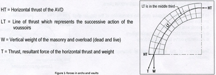
The action of the weight and external forces of a structure create a line of thrust. A line of thrust is the line which defines the equilibrium point between the resultant of the compression forces within the structure against the external actions. The line of thrust is required to stay in the middle third of the arch to ensure stability. The forces in arches and vaults are illustrated in figure 1, taken from a document from The Auroville Earth Institute 'Stability Notions'.
Forces acting in domes
Domes also have thrust lines as a result of their weight and horizontal thrust however a third force is induced; a circular force. This is created as a result of the rotation of an arch around a vertical axis. Horizontal rings are generated from domes built in this manner. The circle force acts within the plan of a ring and can be 'assimilated to the thrust by the force of gravity which acts downwards in the vertical plan' (The Auroville Earth Institute 'Stability Notions').
A dome is generated from the rotation of an arch about a central axis and therefore can be viewed as multiple arches with multiple forces. This network of circular forces and lines of thrust create a net of compression forces over the surface of the dome, which provide resistance to external stresses.
Stresses in the dome
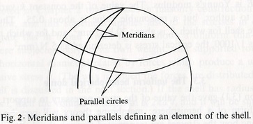
The analysis of a shell is concerned with two stresses: the stress that acts in the meridional direction and the stress that acts in the parallel direction. Meridians and parallels are illustrated in Figure 1, taken from Jacques Heyman 'The Stone Skeleton' (1995).
The analysis of a shell is concerned with two stresses: the stress that acts in the meridional direction and the stress that acts in the parallel direction. Meridians and parallels are illustrated in Figure 1, taken from Jacques Heyman 'The Stone Skeleton' (1995).
'The Meridian plane is created by a surface of revolution through which the meridian (a plane curve) is rotated about an axis lying in the plane of the curve. When such a curve endures imposed loads (externally or due to self-weight) they must be resisted by internal forces' (David Billington, Thin Concrete Shell Structures, 1965).
Continuing with the analysis from J.Heyman, (1995), forces in the shell are considered to be only tensile and compression (discussed later) based on the assumption that the surface has no stiffness against bending. Although a shell structure can be reasonably thin and accommodate safely a range of loads, there is a minimum thickness required to prevent compressive buckling.
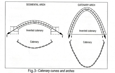
The concept behind this assumption can be explained using the idea of chains. The line of thrust always follows a certain 'shape of an inverted catenary curve' (The Auroville Earth Institute 'Stability Notions'). Imagine a suspended chain under the action of gravity, see figure 3, taken from (The Auroville Earth Institute 'Stability Notions'). The inverted chain represents the line of compressive stresses/thrust line which is centred in the arch for the catenary chain. This central position optimises the behaviour of the arch and is the shape which will provide the greatest stability. Tensile forces will be induced if the thrust line moves away from the centre but the structure will remain stable as long the thrust line remains in the middle third of the structure.
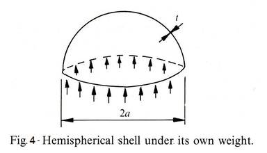
It is observed that like masonry construction domes also have low stresses. This concept is displayed through a simple example of a uniform
thickness hemispherical shell under it own weight. The shell is supported around the base by forces of uniform compressive stress, σ. The dome has radius a thickness t, and a volume of 2π(a^2)t and a unit weight ρ, If the stress from the supports acts on an area of 2πat. Equating the forces will produce the following equation:
thickness hemispherical shell under it own weight. The shell is supported around the base by forces of uniform compressive stress, σ. The dome has radius a thickness t, and a volume of 2π(a^2)t and a unit weight ρ, If the stress from the supports acts on an area of 2πat. Equating the forces will produce the following equation:
Equation 1 above shows the compressive stress required to support the dome. It is independent of the thickness; increasing the thickness, increases the weight but also increases the area involved for support and therefore the effects cancel out.
Further it is expected for a dome of sufficient thickness the loads due to self-weight will be greater than the imposed loads. If the structure is stable supporting its self weight, then any addition imposed loads are negligible as seen with St Peter's.
Modern domes, due to advanced technology are able to be constructed reasonably thin shells minimising the difference between the self weight and imposed loads. In order to ensure the stability of the dome with additional imposed loads further analysis will be required.
It can be noted that local buckling is considered as no real threat for masonry domes.
The uniform hemispherical dome
Building on from equation 1 which evaluated the stress required to support a hemisphere, membrane theory will be used to discuss the transfer of these stresses through the shell. Membrane theory considers resultant stress's N, where N = σt, (t=thickness of the shell). Self weight loads are evaluated in terms of load per unit area, w = ρt. Equation 1 can be written in terms of the above as follows:
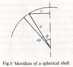
Figure 5 taken from J.Heyman, (1995) represents the meridian of a spherical dome with radius a. Points around the meridian are represented by angle φ and distance r from the vertical. The following relationship can be identified:
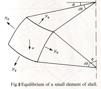
In order to examine stress patterns an infinitesimal element is cut from figure 2. It can be defined by a co-latitude φ and a second co-ordinate θ. Figure 6 taken from J.Heyman, (1995), shows two stress resultants formed at the cut edges to maintain equilibrium of the shell against its self weight.
φ is the stress resultant in the meridional direction and is portrayed in figure 4 as a tensile force however it will actually turn out compressive increasing from the crown(φ =0) to the base of the hemisphere. 'Nθ is the second stress resultant to be analysed which acts in the 'hoop' direction along the parallel circles (shown in figure 1). Both resultants produce two equations, the first being a differential equation' (J.Heyman, 1995):
The second is an ordinary equation (J.Heyman,1995):
A solution to the two equations is given in equation 6, which can then be used to solve for Nθ using equation 5. (Note 'both equations are determined uniquely for a truly hemispherical shell', (J.Heyman,1995)).
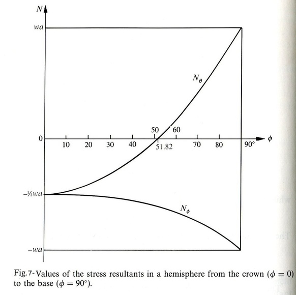
The values obtained from the equations above can be shown graphically by figure 7 taken from J.Heyman, (1995):
Figure 7 confirms the meridian stress resultant Nφ is compressive as stated earlier on. Initial its at a value of 1/2wa at the crown and increases to wa at the base/support. Furthermore it defines the hoop stress at the crown as compressive, converting to tensile at an angle of co-latitude 51.82⁰ (due to the result of [(cosφ)^2 + cosφ = 1 J.Heyman, (1995)]).
Due to the nature of masonry, tensile forces are inadmissible and require a suitable control. Additional steel reinforcement or encircling ties are two methods of resisting tensile stresses.
For further derivations of the fundamentals of stress resultants for shell systems, that are symmetric about there axis of revolution see David Billington's 'Thin concrete shell structures' (1965). This book also identifies the stress resultants for spherical, conoidal, elliptical and conical domes. For the analysis of other types of domes see David Billington's, Robert Maillart's 'Bridges: The Art of Engineering'(1979).
