FELASH (Finite element analysis of thin axisymmestrical shells)
M.Rotter 'users manual' (2011)
FELASH is a suite of finite element programs specially designed for the rapid efficient analysis of thin axi-symmetric shells. The suite consists of two programs PASHA (a common pre processor) and LEASH (the linear finite element program). It allow one to perform the analysis of concrete shell structures.
Finite element method is a numerical technique used to solve differential equations. It is based on the equation F = Ku where f relates to the forces, k is the stiffness matrix and u relates to nodal displacements. It takes a complex problem and separates it into simple equations, it divides a structure up into elements and nodes and creates a mesh. It then connects these elements at the nodes forming a system element matrices which are then solved involving unknown qualities. It then calculates the desired outputs; stress resultants.
Finite element method is a numerical technique used to solve differential equations. It is based on the equation F = Ku where f relates to the forces, k is the stiffness matrix and u relates to nodal displacements. It takes a complex problem and separates it into simple equations, it divides a structure up into elements and nodes and creates a mesh. It then connects these elements at the nodes forming a system element matrices which are then solved involving unknown qualities. It then calculates the desired outputs; stress resultants.
PASHA
This pre-processor program generates the finite element mesh from a limited definition of shell segments and can set up a great variety of different loading conditions on the shell. The program works on a yes, no principle in order to define the necessary inputs and the desired outputs. There are statements programmed into the code to ensure the inputted information is correct. If there has been a incorrect input one can type the opposite to the requirements into the box(as long as its not been carriage returned), for example a number when it specifies a letter and vice versa in order to crash the system resulting in the question being repeated.
The shell is established on a co ordinate system of R, Z and theta as shown in the image below (taken from M.Rotters 'user manual'):
The shell is established on a co ordinate system of R, Z and theta as shown in the image below (taken from M.Rotters 'user manual'):
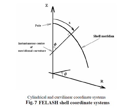
The positive axes are defined as the Z axis in the upward direction and the R axis in the radial outwards direction (shown in figure 7). The shell is defined in terms of the meridional slope and the meridian co ordinate s. The meridian curvature and its rate of change are dependent on the user and the problem at hand. The shell is defined from top down and displacement are defined in the global coordinate system.
The shell is divided into blocks each with uniform thickness and curvature. Again these inputs are dependent on the problem. Once the mesh has been generated a series of questions will be asked related to the structure; material, restraint conditions and so on until all the details of the structure one wishes to analyse are inputted. It then creates a .DAT file which is used later on. This file acts as a template and can be altered for different runs of the program.
The shell is divided into blocks each with uniform thickness and curvature. Again these inputs are dependent on the problem. Once the mesh has been generated a series of questions will be asked related to the structure; material, restraint conditions and so on until all the details of the structure one wishes to analyse are inputted. It then creates a .DAT file which is used later on. This file acts as a template and can be altered for different runs of the program.
LEASH
This is the main linear elastic shell analysis program, used for determining deformations and stress distributions in axi-symmetrically or non-symmetrically loaded orthotropically stiffened branched doubly-curved shells of revolution. This program uses the .DAT produced from PASHA to produce a set of results displaying the corresponding stress and deformations for the inputted shape. These results can be transferred into Excel in order to produce various plots for analysis. The excel file can then be used as a template for inputting the results from multiple runs.
